
Hardware V&V still runs mostly by hand, and the results scatter across notebooks and shared drives. Workflow Logs are the piece of Istari Digital that records the V&V you automate — every result pinned to the exact design version it ran against.
Software automated the grind. Hardware didn’t.
Systems and mechanical engineers lose a significant chunk of their week to repetitive, non-value-add work — manually reconciling data between vendor-locked tools, reworking designs when quarterly meetings expose cross-org dependencies, and executing basic test suites by hand. Software engineers long ago automated this kind of grunt work with CI/CD (continuous integration and delivery) — the approach of automatically compiling and testing code every time someone changes it. Hardware engineering never got the equivalent.
What Istari Digital does
Istari Digital is built to break down the barriers that cause this. It’s an open, programmable hardware product ecosystem that gives no-fail industries agentic access to their existing sources of truth in vendor-neutral, machine-readable formats. That lets teams run automated workflows across tools, collaborate securely across organizational and security boundaries, and execute V&V automatically and auditably.
What Workflow Logs are
Istari Digital provides an SDK (software development kit) for orchestrating complex workflows across your engineering tools. Istari Digital itself brokers the heavy lifting — it executes functions and jobs inside each tool and versions everything it touches. The orchestration that ties those steps together runs where it’s most flexible: in your own scripts, notebooks, and CI pipelines. Workflow Logs are the feature that closes the loop: they let you track those external workflows and tie their results to a specific configuration of your models inside Istari Digital.
Istari Digital terminology
Jobs, agents, and modules are the core of Istari Digital’s architecture. An agent is a small piece of software installed where your engineering data lives. Paired with a module — basically a translator for a specific tool like CATIA or PTC Windchill, or an internal one — the agent runs jobs against that data on command, under the permissions an admin grants and using a provisioned license if required.
Workflows chain those jobs together — and any off-platform analysis — into an end-to-end task, written in Python against the SDK by customers or Istari Digital’s forward-deployed engineers. A Workflow Log then records each run’s result against a configuration of a specific system (a set of models tracked together).
Two examples
The rest of this post walks through two examples to illustrate how you might use Workflow Logs to accelerate engineering work.
The first demonstrates automated V&V on a single part. A design engineer runs a battery of software-defined checks against an L-bracket; when one fails, they revise the design and re-run the checks to confirm the fix. Each result is logged against the exact version of the model using Workflow Logs — an audit trail that builds itself.
The second orchestrates a full design-and-test sweep — CATIA to gmsh to Nastran — to find the wing length for a UAV that maximizes range without breaking. Istari Digital runs and versions every job; a Python script drives the sweep and computes each design’s flight range. Every result is logged, so revisiting the study never means hunting for which CAD version produced which stress number.
Example 1: automated V&V on a design change
This example is fully documented in Istari Digital’s public cookbook — a collection of runnable sample notebooks (“recipes”) for the SDK. Here we walk through it briefly; open the notebook to run it yourself as a learning exercise.
Steps 1–2 lay the groundwork in Istari Digital: connect the SDK, then create a fresh System with the bracket’s STEP file tracked. (You could also create the System by hand in the web app.)
Steps 3–4 run the external workflow: a software-defined battery of checks against the STEP file. It catches that the stress at one of the fillet radii exceeds the allowable limit.
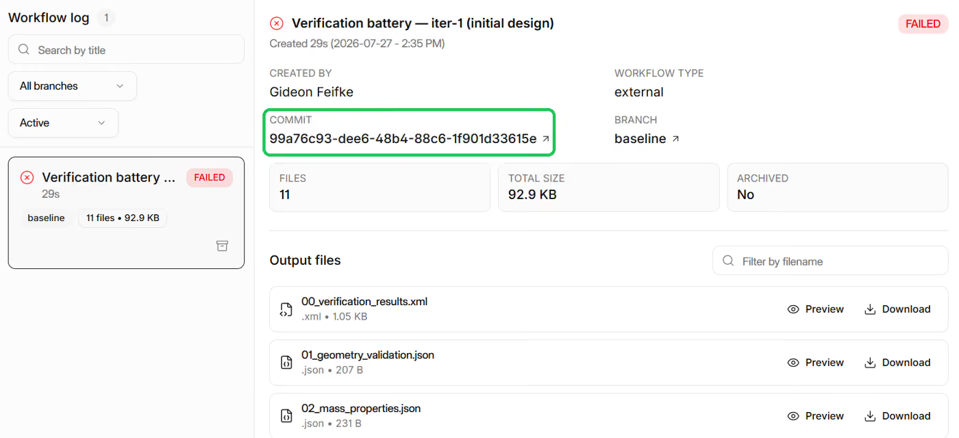
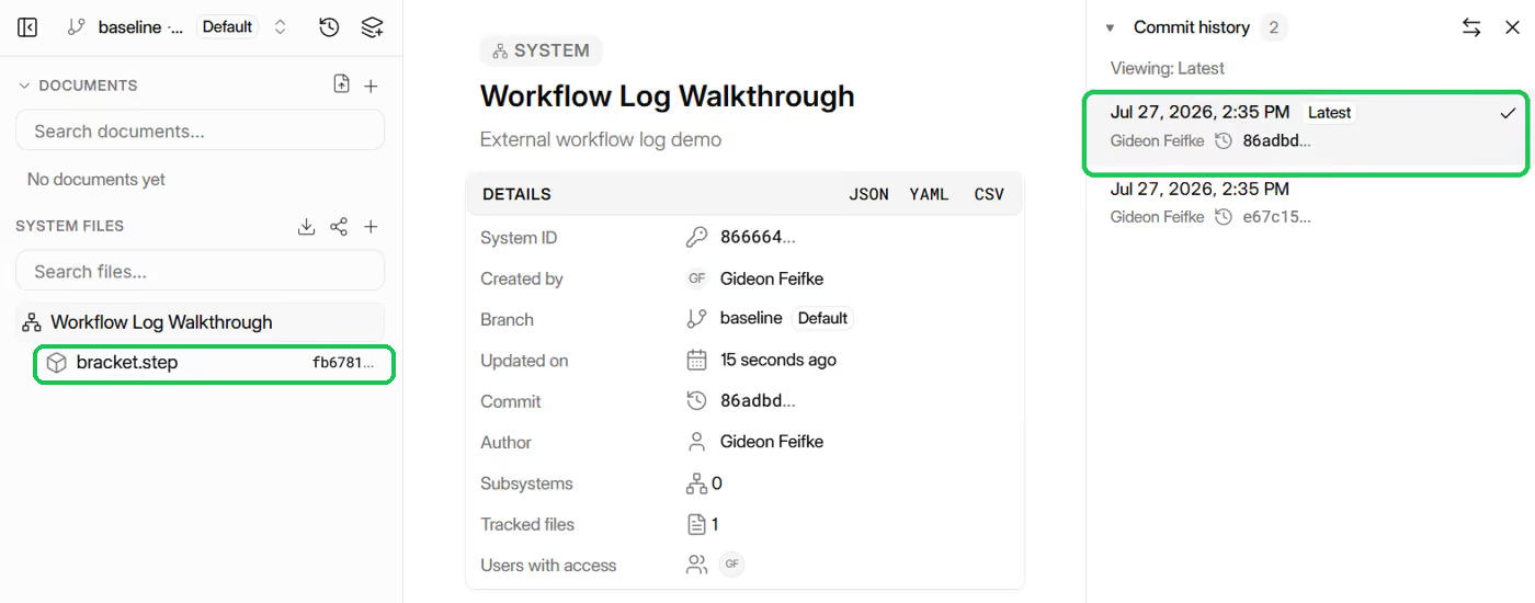
Steps 5–6 are where Workflow Logs come in. The result is recorded in Istari Digital, pinned to the most recent configuration of the System — the one holding that exact version of the STEP file.
Here's what those calls produce in Istari — the Workflow Log entry for the run, and the System commit history it's pinned to:
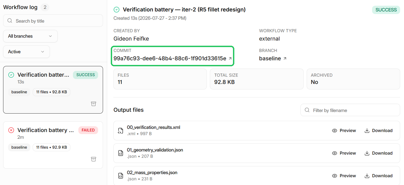
Steps 7–9. The engineer now has the feedback they need. They enlarge the fillet to R5, re-run the same pipeline — this time it passes — publish a second entry, and attach the verified report back onto the model so the evidence rides with the CAD.
After the fix, the same battery passes — here's the second entry it publishes, now sitting alongside the first:
This is a simplified version of a real engineering workflow, but it demonstrates what Workflow Logs unlock.
Today, running CI/CD-style checks on hardware is painful — you find a machine to run the FEA, get access provisioned, wrangle export formats — and even then the result vanishes into whatever notebook you ran it in. With Istari Digital, your engineers run those checks every day, and every verdict lands on the record, pinned to the exact version it tested.
Run it yourself — scenario_a, the design-loop recipe
Example 2: a wing sweep across three tools
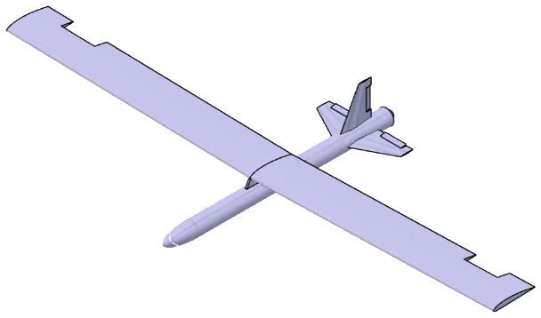
Where Example 1 used a quick calculation to stand in for the stress check, this example orchestrates a workflow across the design tools engineers actually use: it drives geometry in 3DEXPERIENCE CATIA, meshes in gmsh (an open-source mesher), and solves FEA in MSC Nastran. It also shows how Workflow Logs make the resulting digital thread more robust.
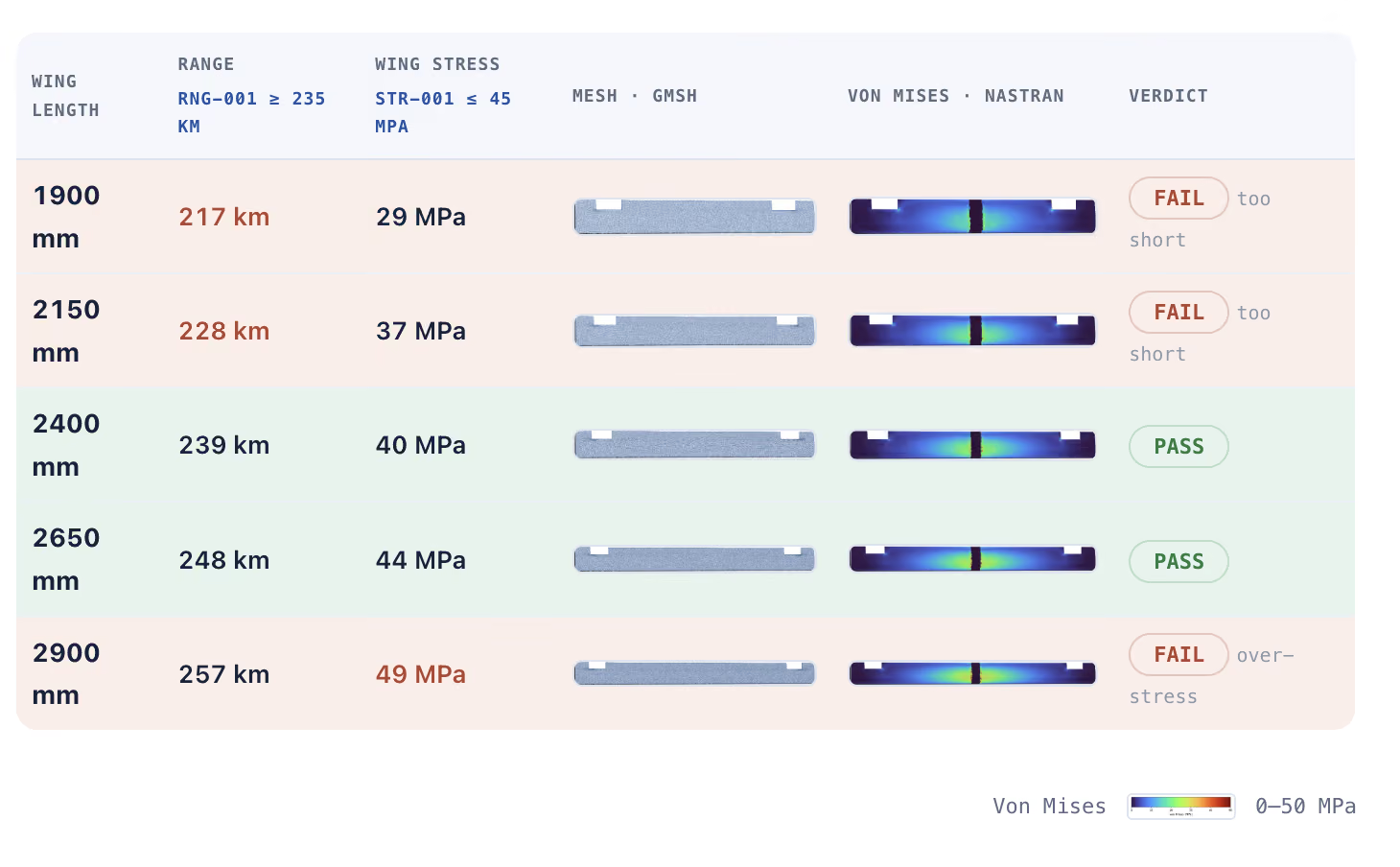
The design challenge is to find the viable range of wing lengths for a UAV. A longer wing gives more lift and more range — but it’s also a longer cantilever, so the stress at the root climbs. Too short and it can’t reach the mission range; too long and the wing can’t take the maneuver load. The answer is the window in between.
The manual loop
The toolchain spans three programs — CATIA, gmsh, and Nastran. By hand, checking a single wing length means being the interface between all of them:
The options today
Without Istari Digital, there are two ways to run that loop across many designs — and neither is good.
Do it by hand and you’re personally clicking through all nine steps for every single design — it’s so tedious that a handful is all anyone ever actually does. Write a custom script and you have to work out how to talk to each tool — and often the specific machine on your network that runs it. Either way, you leave behind no real audit trail, or one buried in a notebook only you can read.
How Istari Digital solves it
Istari Digital orchestrates the loop for you and uses Workflow Logs to build an automatic audit trail as it runs:
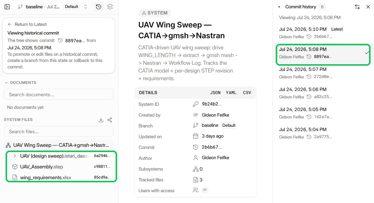
The core of the workflow is one function, evaluate. Its only input is L, the wing length under test, and it runs the five steps of the loop.
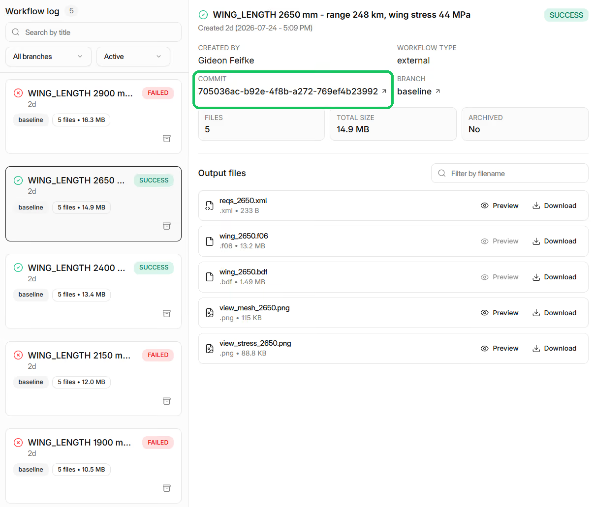
The sweep then calls evaluate across five wing lengths and logs each design against the two requirements. log_design wraps the same create_workflow_output and create_workflow_log_entry calls from Example 1:
Here's that sweep in Istari, in two views — the Workflow Log with one entry per wing length, and the System all five runs share:
The result
With the sweep complete, every design comes together in one view — meshed, solved, and checked.
The payoff
Time. Nobody spends the day clicking through CATIA or babysitting a one-off script. The SDK is the loop — point it at a range of wing lengths and it runs them.
Auditability. Every design is a governed commit with a PASS/FAIL Workflow Log entry. Six months from now, anyone can open the sweep and see which wing length was checked against which requirement, and how it came out.
-
Workflow Logs make V&V part of how you design
Without Istari Digital, V&V is burdensome and slow — so it waits for milestones and gets done all at once, late. With Istari Digital Workflow Logs, your checks run automatically and audit themselves, so V&V stops being a phase at the end and becomes part of how you design — on every change you make, and across every candidate you explore.
And a single engineer’s loop is only the start. Picture the same discipline across a whole program — subsystem integrations checked against each supplier’s latest revision, or an airworthiness case run a hundred times in simulation before the first physical test, every result on the record. That is what unlocks the next level of speed and quality across your org.